Not exactly a project I wanted to do, but one I decided I would try. Auto repair is not my strong suit, but there are many basic repairs that a person can do on their own car.

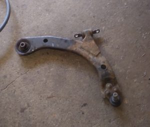
In my case, on my 2006 Chevy Cobalt, there were a rubber bushings on both sides that had dry rotted and separated, and they needed to be replaced for the car to pass inspection.

After going down the youtube rabbit hole, I felt pretty encouraged and decided to give it a try. What needed to be done was relatively simple:

Remove the tire
Remove the control arm, or at least get the end with the bushing exposed
Use a bearing press to remove the old part
Use a bearing press to insert the new part
Put it all back together
With that in mind I took the project on. Now, being a novice at auto repair, what I didn’t recognize was the many steps inbetween those steps. Things I didn’t even think were going to be steps. Unexpected mishaps, stubborn rust, and not having quite the right tool for the job.

Getting the tire off was straightforward. Even getting most of the control arm connections was easy. There are 3 places the control arm connects to: two points on the subframe and one point on the wheel assembly. There are 4 bolts total to remove before it is loose.

My first approach was to only remove two of the three connections and pivot the bushing so it was accessible. I had seen someone do this in a video, so I knew it was possible. It proved to be too difficult though, and I gave up on that approach after hours of fighting it. My best guess was the shock spring was creating a lot of strain and making it hard to get a good angle to get the bushing out.

After giving up on this approach, trying to reassemble things also proved more difficult that advertised, again because of the spring. The bolts on the subframe weren’t aligned enough to engage properly, so I eventually figured out I needed to use a spring compressor to relieve some of the pressure so I could get it into alignment. Using a spring compressor is easily one of the most terrifying things I’ve done, and thinking back I wish I had been wearing a faceshield and stood more out of the way in case that thing let go.

An additional note on assembly: all of the bolts have specific torque values they should be tightened to. I looked this up through AutoZone’s site, they have a bunch of the technical documents and details for that.

Okay, so lesson learned. The spring is a problem, and I can’t ignore it. The next time I went in, I removed all the bolts and moved the strut out of the way. Even then it still took some finangling to get the control arm out, but I got it.

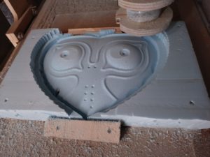
The bearing press tool wound up being a crapshoot. It was a loaned kit from an auto parts store with a bunch of different sizes. Of course the size I needed wasn’t there, so I rummaged around the shop and found some scrap pipe that juuuust fit.

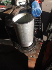
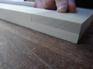
For the removal and installation to go well, the pipe size has to match the outer diameter of the bushing. Can’t press on the inner section or you’ll tear up the rubber. Can’t press on the rubber either. And it is a VERY tight fit, so the amount of force required is substantial.

Removal wasn’t too terrible on the first one, I think I managed to press it out on the first try (it might have needed a little encouragement with the air hammer). One important thing: the hole in the control arm is TAPERED, so the bushing goes in one way, and it has to be removed the other way.

I bungled the first attempt at installing the new one. Luckily I bought two. What happened was basically not being careful enough when aligning the bushing and instead of going straight into the hole it started going diagonally. Once that happened it crushed one side, and that was not fixable by my abilities. After some swearing, I did some more video-watching and learned someone used a light amount of oil when installing theirs. That seemed iffy, but it was worth trying. Between that and being extra careful, it went in straight and true!

Alright, that’s that. Got the control arm reinstalled, and since I was already familiar with how that goes it went pretty smooth. I couldn’t replace the other one right away since I wrecked one of the two I bought, so I bought another two (just in case) and tried it again when the parts came in.

Things were going pretty ok until I got to the bolt for the bushing. This one was being incredibly difficult and I couldn’t figure out why. Eventually the signs were obvious, it was spinning in place and was probably stripped.

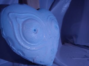
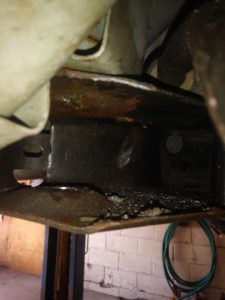
After about 8 hours, I finally figured out what was REALLY going on and what to do about it. Using the camera on my phone I got a look up and around the bracket to see this.

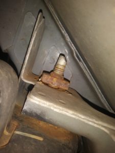
The threaded portion was just this square nut that had (at one point) been welded to the subframe, but had since let go. It must have corroded enough so that when I used the impact wrench to loosen the bolt it jerked the nut free. Unfortunately this was in an incredibly tight spot, and the nut was very stuck on there. I struggled with that for another 3 hours or so and had a brilliant though – I’ll just weld it back in place! I can’t fit a wrench in there, but I can fit a MIG welder gun in there.

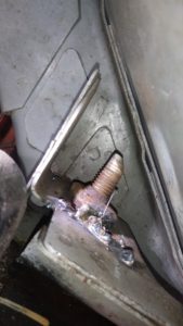
Not my proudest work, but that was enough. I worked slowly and used a lot of PB blast, and thankfully that was enough. Until I went to remove the bushing, which was also substantially rusted and had fused to the bolt. The rubber had also separated from the center steel part and spun freely. I could move the bolt only so far because of the way the bushing assembly is.

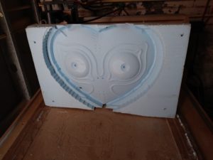
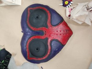
Here is a picture of the subframe where the bushing goes into (bushing not pictured).

I’ll keep a long story from getting much longer and summarize the rest:

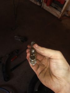
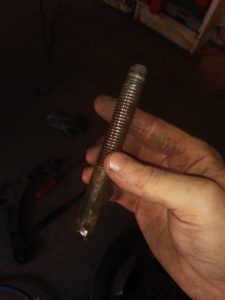
I cut away as much of the bushing as I could (the rubber and outer steel part), then I get some vice grips to hold onto the remaining piece of the bushing that the bolt was stuck to. Then I started a lot of drilling, trying to hollow out the bolt until it was no longer attached to the bushing. When drilling out bolts, I start with a small diameter to make an easy pilot hole as deep as I can, and gradually increase in size.

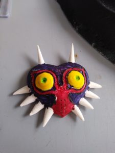
Eventually this paid off, and I got something that looked like this.


Since I destroyed that bolt, I went out and bought a replacement, and went through the process of cleaning up the rust on the control arm, getting the new bushing in, and getting it all back together. I was a pro at the reassembly at this point, so that went well.


0/10, would not do again.

Making an 8ft Wide Picture Frame

My friend’s father asked me if I knew anyone that could build a very large picture frame. Being the aspiring maker I am, and having built zero picture frames before, I said “sure, how hard can it be?”

The basic features of this frame were that it needed to hold this photo of a beach, which was actually made of 8 or 9 8.5″ x 11″ sheets glued to a stiff backer board.
It also needed to hold a piece of glass slightly larger than this photo.
The two stylistic requirements were that it be done with a half-lap joint, and have two dowel joints in each corner for cosmetic purposes.

In order to build this, I needed to do the following:
Cut the 4 sides to length
Make the half-lap joints
Make the recess on the back of the pieces to accommodate the thickness of the glass and the photo
Glue the joints together
Drill holes and insert dowels in the corners

That’s it! And as long as everything goes to plan, it shouldn’t take very long. *wink*

Just to be sure I got the process right, I decided to make a mini version of the frame. Same features, same board thickness, just much smaller frame width and height.
It wound up taking the better part of 3 days, but I wound up learning a lot from doing the first one.

In order to make the half-lap joints, my solution was to use a hand router in a custom-built jig.

It was mostly made from really nice scrap MDF around the shop. The thickness was a little shy of the stock material, so I wound up shimming it with some washers.
The basic premise was I could stick just the end of the board in this jig, have it meet up with a specific marking or endstop, and just move the router around within the constrained area.
The board would be clamped initially just by a C-clamp, but later I devised a setup that used a rounded-off wood screw and a piece of scrap oak to act as a cushion between the screw and the board.

This setup worked great! Because I made the opening just big enough to hold these boards, it held things pretty consistently and tightly, which meant all the cuts were really consistent. Not perfect, but thankfully they didn’t need to be. His criteria for the style was to look old and handbuilt, so any minor flaws actually help sell the look.

To do the recess for the glass and photo, rather than try to use the table saw to do a cut in the middle of a piece, or to cut a groove all the way through and leave a couple of open spots on the sides of the frame, I used a router table.
I was able to make markings on the workpiece and on the fence of the router table so I knew where my start and end points were. I could have used endstops instead for more consistency, but it didn’t seem necessary.

This is how the little frame came out. The lap joints had a really close fit with minor gaps here and there, but it was nothing a little wood glue couldn’t fill in.

It just so happened to fit a rectangular ceramic tile I got for a totally separate project! I love it when a lack of a plan comes together.

One important thing I learned is that it helps to do the lap joints first before routing the groove for the picture on the “back”. If there’s a mistake or blowout on one side you can put that on the backside. No one will ever see your shame.

Since the small frame went well, I decided to go for making the big one. Only issue was I didn’t get around to it for another month or two, and I had forgotten a lot that I learned from the first one.
That included what the lengths of thing should even be, and I wound up starting a work session cutting my stock too short and needed to buy more to replace it.
Mistakes happen sometimes, and when that happened I decided the only thing I should do that day is buy replacement wood and try again tomorrow. Once the mistakes start showing up they tend to bring friends.

Fast forward a bit, and the larger frame is mostly done! The lap joints went pretty smoothly, and the inner recessed edge has also been routed out.

A close-up of one of the better half-lap joints. This is the beauty of a well-made jig.

The final assembly after gluing it up and putting oak dowels in the corners. It’s hard to convey just how gigantic this wound up being.

When all was said and done, he liked the result and planned to take care of the rest – getting the glass and applying stain.
I imagine it’s now hanging up at a beach house, adding to an already rustic style.

Majora’s Mask made of foam

Being a child of the 90s, I grew up playing video games. I was usually behind the current trends since our family couldn’t afford to spend a ton of money on video games, but when I eventually got to play Legend of Zelda: Majora’s Mask, it was instantly one of my all time favorites.

I’ve always wanted to make numerous items from the LoZ games – the master sword, an ocarina, a fairy in a jar that could save me from the brink of death, all of that. But I typically didn’t have the money to be putting into those types of projects.

Well years later, when I wasn’t broke and had access to a CNC Router, I decided a fun project would be creating Majora’s Mask out of foam. This was a couple of months before the local halloween parade, so I figured it could be a fun project that I could show off. There are numerous 3D files out there for the mask – the one I probably used was by ferreusveritas on Thingiverse.

My strategy was to make it as large as I reasonably could, at least to obscure my whole face. It also needed to not take forever to cut, as I knew 3D carvings on a CNC router take an awful long time and I don’t like babysitting the machines.

I scaled it to be about 14″ wide by 12″ tall, and about 2″ deep. It’s as tall as my head is, but more than twice as wide. Before that I also removed the spikes, as they stick out very far and I didn’t want to have to carve out a lot of extra foam for that. The spikes can be made separately in a much shorter time, and ultimately I just made some paper cones and glued them on.

Below is the foam on the CNC in various stages. It was so satisfying to watch.

The first pass was using a 1/4″ endmill and taking some fairly deep passes. If memory serves it was 1/2″ depth of cut per pass. Foam like this cuts SO WELL, I had no idea. First time working with it and it was magical. I was able to really turn up the feedrate too.

The second pass was using a 1/4″ ball endmill to get the smooth curves of the mask. My stepover was maybe 1/8″, and it did wind up leaving a bunch of ridges, but after a bit of sanding and some compromises due to a short timeframe I got it good enough.

Glorious! The carving went great for a first-time attempt at a new material, and for something this size. There were a couple of issues though. I must have set the starting depth a little too high, and it wound up leaving some flat spots on the highest parts where it didn’t cut. Not being much of a perfectionist, I figured I could sand it and blend it in. There was also a small hole that was revealed after carving in the bottom-left side of the mask, but that’s easy enough to fill in with glue.

To free the mask from the block, I cut around it using a bandsaw with a narrow blade and followed just outside the shape. I then sanded down the edges.

The backside of the mask was going to be cut on the CNC as well, but for time’s sake I decided I would just carve it out manually. Mostly I used one of those long retractable utility knives and took many V-shape cuts. It started with larger chunks, and bit by bit was cut down into smaller chunks. Once it got close I started to sand it to be roughly the same shape as the outside of the mask. Appearance didn’t matter since it would be the backside, but it should sit evenly on my face so I couldn’t leave it too misshapen.

To prepare the foam for painting, I had already learned from a previous project that spray paint and foam DO NOT MIX. Or rather, they do mix. The solvents in spray paint mix especially well with foam and begin to dissolve it. To avoid that, I first covered the entire thing in a few layers of elmers glue (mod podge would have also worked). This creates a good seal over the foam, and does not react to spray paint. It took a few days between coats due to the long dry time – it was a lot of glue.

Once I felt confident I didn’t leave any bare spots, I took it outside and spray painted the whole thing in black.

For the details, rather than try to spray paint and mask it all (ba-dum-psh) I went for a brush type paint. Not having much experience, I figured acrylic paint would be easiest. For practice I 3D printed the file I used at a very small scale.

With that I was able to do some color-matching with small amounts of acrylic paint, and I got a general understanding of the ratios of colors I needed to mix to get the main details down.

After that I went full-scale and mixed up a bunch of paint.

And here is the “finished” paint job, or the final paint job I put on it. There were many smaller details that I decided I didn’t have time for, as the halloween parade was quickly approaching.

I had quite a bit of leftover paint, mostly from the larger sections of the mask, so I decided to make some abstract art. Rather than using brushes I just smeared it with some wood scraps onto a square of plywood. I actually still have this hanging up on my wall.

So now that the mask was painted, I was still missing a big piece of the mask: the spikes! That should be the easy part, just make some paper triangles and wrap them into a cone shape. Well it took some trial and error, but I eventually got it to the shape and size I wanted. I wrapped them into shape, taped them, then coated them in elmers glue so they could be painted as well. The paper is less susceptible to spray paint, but very susceptible to being wet in general. I used acrylic paint for these, but even acrylic paint can dampen the paper and deform them, hence the elmers glue coating.

Once all the cones were dry and stiff, they needed to be attached to the mask. An elegant solution was to cut a groove in the foam and then gently cram the open end of the cone into the groove. I believe I added some elmers glue to the area to help it stay in place.

Attached all the cones, attached some string on the backside so it can be worn and… it’s ready for halloween!

All in all, it was a very fun project. I got to make something from one of my favorite childhood games, I used a CNC router to make something large, got some practice painting, did a lot of kludging to get things to work, and had a lot of fun walking in the halloween parade with it. There was some more to the costume I didn’t cover in this article, mostly picking out some clothes that match the character’s colors, making some quick gloves and a shoddy hat, covering some normal shoes with orange cloth.

You’ve met with a terrible fate, haven’t you?